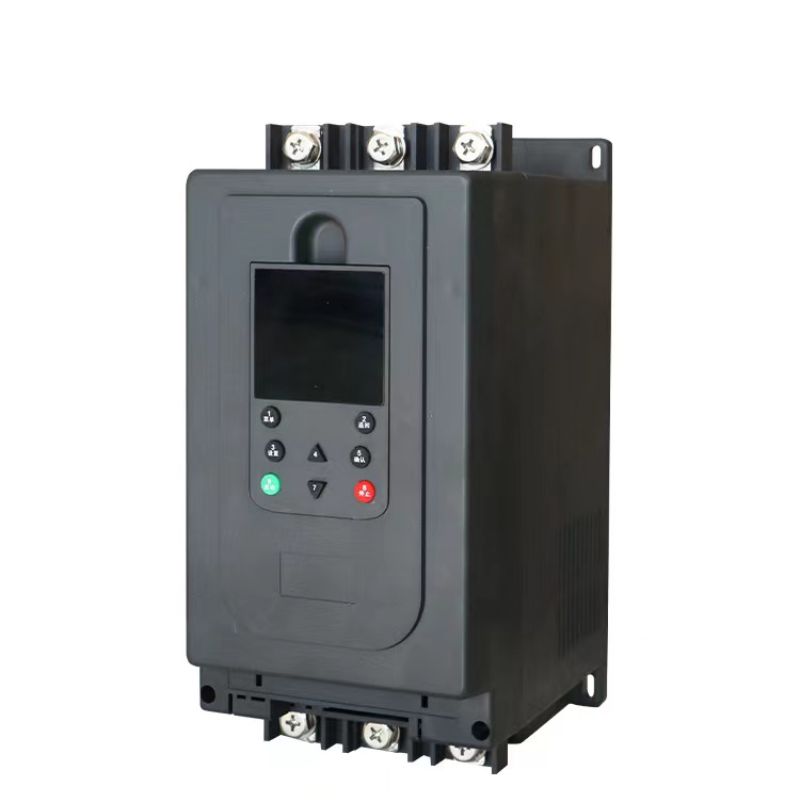
Intelligent High Quality Multi-function 3 Phase 380V AC Electric Motor 22-630KW Online Soft Starter For Motor
Chapter 1 Precautions before Use
1.Arrival Inspection
Check the nameplate to verify if the machine is the one ordered,if the product model and power specifications are
correct,and if the packaging is damaged.If there are any discrepancies,please contact the manufacturer or local
authorized distributor.
2.Operating Environment
| item | Specifications |
| Standard | GB14048.6/IEC60947-2-2:2002 |
| Three-phasepower supply | Voltage(AC)380V±15%(220V and 660V optional) |
| Frequency | 50/60Hz |
| Applicable motor | Squirrel-cage three-phase asynchronous motor |
| Starting frequency | When the motor is fully loaded at startup,do not exceed 4 times per hour.It is recommended not to exceed 10 times per hour under no load or light load. |
| Protection leve | IP20 |
| Shock resistance | Compliant IEC68-2-27:15g,11ms |
| Seismic capacity | Altitude below 3000 meters,vibration intensity below 0.5G |
| Operatingtemperature | Operating temperature:0 to+40C without derating (between+40C and 60℃,for every 1℃ increase,current decreases by2%)and below 60℃ |
| Storage temperature | -25℃~70℃ |
|
Environmental humidity |
93%without condensation or dripping,compliant with IEC68-2-3 |
| Maximum workingaltitude | Derating not required within 1000 meters above sea level (above 1000 meters,current decreases by 5%for every additional 100 meters) |
| Cooling method | Natural cooling ai |
|
Relative and vertica |
Vertical installation,tilt angle range within±10℃ |
Chapter 2 Precautions before use
3.Installation Requirements
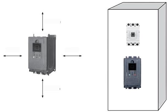
3.1 The soft starter should be instaled vertically. Do not instal it upside down. at an anale. or horizontallv, it should beinstalled with screws on a solid structure.
3.2 When the soft starter is running, it will generate heat. To ensure air circulation, it should be designed with a certainamount of space as shown in the diagram. Since the heat is emitted upwards, it should not be installed beneathheat-sensitive equipment.
Chapter 3 Unique Features of the Soft Starter
◆Wide screen design for abundant and more aesthetically pleasing information;
◆ Wide adaptation to power voltage range,suitable forAC250V-500V power grid voltage;
◆Real-time display of voltage and current calibration face (inaccurate current can easily lead to a series of problems, such as excessive starting time,overload protection inaccurately burning the motor,etc.);
◆The high or low voltage of the grid does not significantly affect the starting performance,avoiding difficult starting
when the voltage is low;
◆The use of pulse transformer to drive the thyristor,with low failure rate and high trigger torque,capable of handling heavy loads such as ball mills;
◆ Multiple start-up modes to meet the needs of various equipment;
◆Accurate fault localization,for example,phase loss fault can pinpoint the specific phase loss,facilitating on-site maintenance;
◆ Comprehensive protection functions,including pre-start input/output phase loss and thyristor short-circuit diagnosis,with the option to selectively disable all protections;
◆ Support for frequency synchronization suitable for generator power supply;
◆ Support for dual panels,with universally designed Ethernet interfaces;
◆ Three programmable relays for flexible adaptation to various on-site applications;
◆ Current control type(specifically designed for crusher and feeder linkage);
◆Thyristor short-circuit interlocking protection (requires matching excitation release and disconnection switch to ensure that the thyristor breakdown does not burn the motor);
◆ Featuring a power-on restart function,caution is advised due to safety considerations in its design;
◆ Equipped with time limit usage and release functions,effectively maintaining the interests of the seller;
◆ Records fault information for troubleshooting and maintenance by after-sales service personnel;
◆Records operating time for after-sales service maintenance;Cloud control development in progress for future technology;
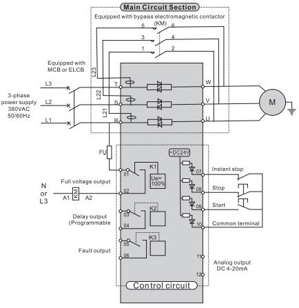
Chapter 4:Diagrams of Primary and Secondary Wiring Principles and Main Circuit Schematic of Bypass soft starter

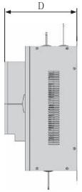
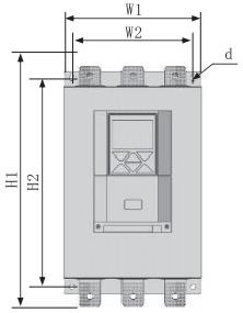
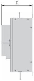
Chapter 5:External Shape and Installation Dimensions of Bypass soft starter
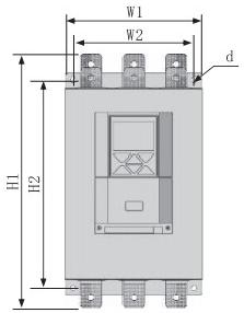
|
Model&specifications |
Outline dimensions(mm) | Installation dimensions(mm | Weight(kg) | ||||
| W1 | H1 | D | W2 | H2 | d | ||
| 22-75kW | 145 | 280 | 160 | 120 | 240 | M6 | <3.5 |
| 90-220kW | 260 | 490 | 215 | 230 | 390 | M8 | <20 |
| 250-350kW | 300 | 530 | 215 | 265 | 425 | M8 | <25 |
| 400-450kW | 340 | 570 | 215 | 305 | 470 | M8 | <30 |
| 500-630kW | 410 | 670 | 250 | 345 | 550 | M8 | <40 |
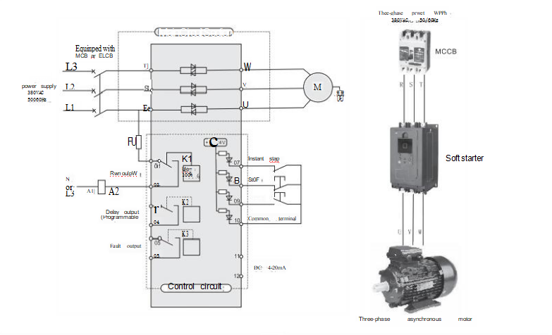
Chapter 6:Diagrams of Primary and Secondary Wiring Principles and Main Circuit Schematic of Online soft starter
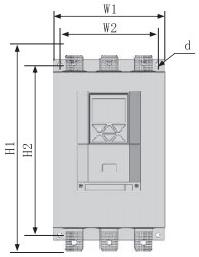
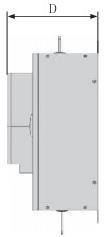
Chapter7:External Shape and Installation Dimensions of Online soft starter
|
Model&specifications |
Outline dimensions(mm) | Installation dimensions(mm) | Weight(kg) | ||||
| W1 | H1 | D | W2 | H2 | d | ||
| 22-75kW | 155 | 310 | 200 | 85 | 280 | M6 | <5 |
| 90-115kW | 230 | 370 | 250 | 150 | 330 | M8 | <15 |
| 132-160kW | 360 | 425 | 250 | 260 | 390 | M8 | <20 |
| 185-220kW | 360 | 425 | 250 | 320 | 430 | M8 | <25 |
| 250-400kW | 415 | 500 | 275 | 370 | 510 | M8 | <30 |
| 450-630kW | 700 | 650 | 330 | 560 | 660 | M8 | <50 |
Chapter 8:External Shape and Installation Dimensions of V type soft starter
| Model &specifications | Outline dimensions(mm) | nstallation dimensions(mm) | Weight(kg) | ||||
| Wl | H1 | D | W2 | H2 | d | ||
| 22-75kW | 144 | 283 | 190 | 128 | 261 | M6 | <5 |
| 90-115kW | 215 | 380 | 240 | 162 | 355 | M8 | <15 |
| 160-250kW | 255 | 410 | 240 | 162 | 385 | M8 | <20 |
| 320-400kW | 415 | 535 | 265 | 323 | 500 | M8 | <30 |
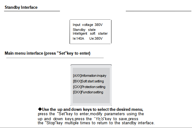
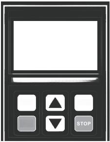
Chapter 9:Chinese Menu Display and Parameter Operation Instructions
Chapter 10:Start-Up Setting
| Function code | System name | Parameter range | Factarydefault value | Communication address | Parameter description |
| B00 |
Motor rated current |
5~2000A | Mode
determination |
0 | For initial use,it is essential to modify this parameter to the actual currentvalue on the motor nameplate,as
motor protection is based on this value;otherwise,it may lead to protection failure and motor burning |
| B01 | Starting mode | 0.Voltage ramp 1.Current ramp | 0 | 1 | |
| B02 | Initialvoltage/current | Voltage mode (25~80%)Ue Current mode (25~80%)le | 40% | 2 | |
| B03 | Ramp rate | 0~120 | 10 | 3 | |
| B04 | Current limit multiplier | 100~500%le | 350% | 4 | |
| B05 | Soft stop rate | 0~60 | 0 | 5 | |
| B06 | Jump voltage | 50~100%Ue | 80% | 6 | |
| B07 | Jump time | 0~5S | 0S | 7 | |
| B08 | Delay start time | 0~600S | 0S | 8 | |
| B09 | Grid frequency | 0:50HZ 1:60HZ | 0 | 9 |
Chapter 11:Protection Setting
| Function code | System name | Parameter range | Factory
default value |
Communication address | Parameter description |
| C00 | Overcurrent protection | 80~500% | 150% | 14 | Set to 80 to close overcurrent protection |
| C01 | Overcurrent
protection trip time |
0~30S | 2S | 15 | |
| C02 | Current imbalance
threshold |
10~100% | 50% | 16 |
Set to 100 to close current imbalance protection |
| C03 | Current imbalance
threshold trip time |
0~30S | 3S | 17 | |
| C04 | Underload protection | 30~100% | 100% | 18 | Set to 100 to close underload protection |
| C05 | Underload protection trip time | 0~30S | 5S | 19 | |
| C06 | Motor overload level | 10A,10,20,30,OFF | 30 | 20 | |
| C07 | Motor stall multiplier | 5~10le | 6 | 21 | Set to 5 to close stalling protection |
| C08 | Phase sequence
detection |
0.close 1.open | 0 | 22 | |
| C09 | Start-up timeout | 5~120S | 60S | 23 | |
| C10 | Overvoltage protection | 100~150% | 130% | 24 | Set to 100 to close overvoltage protection |
| C11 |
Undervoltage protection |
40~100% | 50% | 25 | Set to 100 to close undervoltage protection |
| C12 | Over/undervoltage
protection trip time |
0~30S | S | 26 | |
|
C13 |
SCR short-circuit gain |
5~20 |
5 |
27 |
For example,with a Current transformer ratio of 500/5,when any programmable relay selects the SCR short-circuit output and activates the
protection,if no trigger occurs,and any phase exceeds 500*2%+5=15A,the protection will be riggered and a fault will be reported |
| C14 | Phase loss delay | 0~5S | 3S | 28 | |
| C15 | Protection parameter reset | 0 | 29 | Input 10 is valig |
Chapter Twelve Function Setting
| Function code | System name | Parameter range | Factory
default value |
Communication address | Parameter description |
|
D00 |
Control Mode |
0.Keyboard 1.Terminal 01 2.Keyboard Terminal 01 3.Terminal 11 4.Keyboard Terminal 11 |
0 |
33 |
Wiring Instructions (Terminal 01,One Normally Open and One Normally Closed)
Three-Wire System:X1-COM,red button switch normally closed (stop),X2-COM,green button switch normally open (start) Two-Wire System:X1 and X2 short together-COM,closed to start,open to stop when powered on,the point is closed and the motor will start automatically.Suitable for float switch water supply control,use caution with mechanical drives! Wiring Instructions (Terminal 11,Two Normally Open): Three-Wire System:X1-COM,red button switch normally open(stop),X2-COM,green button switch normally open (start) This function is suitable for use in situations with significant vibration,where button switches using normally open contacts will not automatically stop due to poor contact.This function is suitable for water supply control using electric contact pressure gauges,without the need for intermediate wiring,simple and reliable,reducing failure rates Note:External control terminals are DC24V active signals and may not accept other power sources.It is best to keep the maximum lead length within 10 meters |
|
D01 |
DC Output Mode | 0,4~20mA
1.0~20mA |
0 |
34 |
Chapter Thirteen Function Setting
| Function code | System name | Parameter range | Factory
default value |
Communication address | Parameter description | |
|
D02 |
DC Correspondence |
0.0~le 2.0~3le 4.0~5le 6.0~2Ue | 1.0~2le
3.0~4le 5.0~Ue |
1 |
35 |
|
|
D03 |
DI Terminal Function |
0.Fault Reset 1.Momentary Stop Protection |
0 |
36 |
Fault reset:Dl-COM is normally open momentary operation resets the fault
Momentary stop function:Dl-COM is normally closed,generally used to interlock with an external protection switch normally closed contact.Opening that will result in unconditional stopping and "momentary stop" will be highlighted on the LCD screen |
|
|
D04 |
K1 Function Programming |
0-Start Closed
1-Run Closed 2-Soft Stop Closed 3-Full Closed 4-Fault Closed 5-Silicon Short Circuit Closed 6-Start Open 7-Run Open 8-Soft Stop Open g-Full Open 10-Fault Open 11-ilicon Short Circuit Open 12-Feeder Function 13-Delay Closed |
1 |
37 |
Feeder function,action value setting parameters C19-C22 |
|
Chapter Fourteen Function Setting
| Function code | System name | Parameter range | Factory
default value |
Communication address | Parameter description |
| D05 | K1 Programming Delay | 0~60S | 0S | 38 | |
| D06 | K2 Function Programming | Same as above | 5 | 39 | |
| D07 | K2 Programming Delay | 0~60S | 0S | 40 | |
| D08 | K3 Function Programming | Same as above | 4 | 41 | |
| D09 | K3 Programming Delay | 0~60S | 0S | 42 | |
| D10 | Communication Address | 1-32 | 1 | 43 | |
| D11 | Baud Rate |
0-(4800),1-(9600),2-(19200) |
1 | 44 | |
| D12 | Communication Control | 0-Close 1-Open | 1 | 45 | |
| D13 | User Password | 0-9999 | 0 | 46 | Universal password 123,0 to close |
| D14 |
Phase ACurrent Coefficient |
100~500 | 一 | 47 | |
| D15 |
Phase B Current Coefficient |
100~500 | 一 | 48 | |
| D16 |
Phase C Current Coefficient |
100~500 | 一 | 49 | |
| D17 | DC Coefficient | 100~500 | 一 | 50 | |
| D18 | Voltage Coefficient | 100~500 | 一 | 51 | |
| D19 | Current Closing Value | 0~80% | 30 | 52 | |
| D20 | Current Closing Delay | 0~10S | 1S | 53 | |
| D21 | Current Opening Value | 50~100% | 80 | 54 | |
| D22 | Current Opening Delay | 0~10S | 1S | 55 |
Chapter Fifteen:Display Panel Operation Instructions and Opening Size Diagram
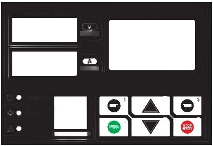
1.Keyboard Panel Operation Instructions and Opening Size Diagram
The keyboard panel has rich operational functions,such as running and stopping operations,data confirmation and modification, and various status confirmations.
Chapter Sixteen:D-Type Online Soft Starter
2.Functions of Keyboard Buttons
| Button Name | Main Function |
| Setting Key-1 | Press this button to enter the main menu;corresponding to the number pad |
| Up Key-2 |
Press this button to select relevant parameters;corresponding to the number pad 2 |
| Confirm Key-3 | After selecting the required parameters,press this button to save;corresponding to the number pad 3 |
| Start Key-4 | n standby mode,press this button to start the motor;corresponding to the number pad 4 |
| Down Key-5 |
Press this button to select relevant parameters;corresponding to the number pad 5 |
| Stop Key-6 | Press this button to stop when in running status;press this button to reset in case of a fault;corresponding to the number pad 6 |
 |
1.If a password is required,please use the corresponding number pad.2.Press the stop button to reset in case of a fault
3.Press the setting button to enter,then use the up and down keys to select the required parameters,and press the confirm button to save |
Chapter Seventeen D-Type/V-Type 90-400KW
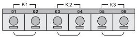
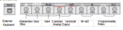
1.Terminal Wiring Instructions
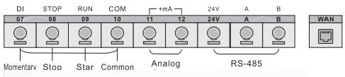
Chapter Seventeen D-Type/V-Type 90-400KW
1.Terminal Wiring Instructions
|
ass ficalion |
TerminalMarking | TerminalName | Function Description |
|
Contact Output |
01,02 | Start to topwithout delay output (closed) |
01,02 is for closing bypass contactor or operation indicator light after soft start completion FU -L1 凸 - |
| 03,04 | When startingcommand
ssued (closed) |
03,04 is for programmable circuit breaker output,delay time set by code F4.Output function set by code FE,is normally open contact,closes when active.(Contact capacity AC250V/3A) | |
| 05,06 | When fault
occurs(closed) |
05 and 06 are programmable fault relay outputs.They are closed when the soft starter fails or oses power,and open when the power is connected.(Contact capacity:AC250V/3A) | |
| Contact nput | 07 | Momentary stop input | Motor stops immediately when 07 and 10 are open (or connected in series to other protector's normally closed contact) |
| 08 |
Soft stop inpu |
Motor executes deceleration soft stop when 08 and 10 are open (or stops on its own) | |
| 09 | Start inpu | Motor starts running when 09 and 10 are closed | |
| 10 | Commonterminal | Common terminal for contact input signals | |
| Analog Output | 11,12 |
Analog output |
11,12 can measure current signal varying with the load,outputs 4-20mA,calibrated at 400% calculation formula:D=400/16(Ix-4).Where Ix is the measured current actual value (mA) D is the motor load current (% |
| RS-485 | GNDAB External network port (contact the manufacturer for communication address) | ||
Chapter Eighteen Display Panel Operation Instructions and Opening Size Diagram
1.Keyboard Panel Operation Instructions and Opening Size Diagram
The keyboard panel has rich operational functions,such as running and stopping operations,data confirmation and modification, and various status confirmations.

Chapter Nineteen V-Type Online Soft Starter
2.Functions of Keyboard Buttons
| Button Name | Main Function |
| Menu Key-1 | Press this button to enter the menu,corresponding to number pad 1 |
| Back Key-2 | Press this button to return,corresponding to number pad 2 |
| Setting Key-3 | Press this button to enter options,corresponding to number 3 |
| Up Key-4 | Press this button to select downward,corresponding to number 4 |
| Confirm Key-5 | Press this button to confirm and save,corresponding to number 5 |
| Start Key-6 | Press this button to start,corresponding to number 6 |
| Down Key-7 | Press this button to select downward,corresponding to number 7 |
| Stop Key-8 | Press this button to stop,corresponding to number 8 |
 |
1.If a password is required,please use the corresponding number pad.2.Press the stop button to reset in case of a fault
3.Press the setting button to enter,then use the up and down keys to select the required parameters,and press the confirm button to save. |
Chapter Twenty Control Board Terminal Definition
1.Terminal Wiring Instructions
V-Type 22-75KW
| Classification | Terminal Symbo | Terminal Name | Function Description |
|
Contact Input |
1 | Momentary stop input | Motor stops immediately when 1 and 4 are open (or connected in series to other protector's normally closed contact) |
| 2 | Stop input | Motor executes deceleration soft stop when 2 and 4 are open (or stops on its own | |
| 3 | Start input | Motor starts running when 3 and 4 are closed | |
| 4 | Common
terminal |
Common terminal for contact input signals | |
| Analog
Output |
4,5 | Analog Outpu |
4,5 can measure current signal varying with the load,outputs 4-20mA,calibrated at 400% |
| RS-485 | 6,7 | AB External network port (contact the manufacturer for communication address | |
| Contact
Output |
8,9 | K2A\K2C | Programmable relay output |
| Chapter Twenty-One Fault Description | |||
| Fault
Code |
Fault Name | Fault Reason | Solution |
| 01 | Input phase loss | Phase loss during
start-up or operation |
Check if the three-phase power supply is reliable,adjust phase loss delay (C14) |
| 02 |
Output phase loss |
Load phase loss or
thyristor breakdown |
Check load wiring,see if thyristor is broken down |
| 03 | Overcurrent
during operation |
Sudden load increase
excessive load fluctuation |
Observe load condition,adjust overcurrent protection (C00),and adjust overcurrent time (C01) as appropriate |
| 04 |
Current imbalance |
Unbalance three-phase
currents of equipment |
Observe if motor start-up or operation is smooth,adjust current imbalance (C02),and adjust current imbalance time (C03)as appropriate |
| 05 | Power supply
reverse |
Phase sequence reverse | Adjust phase sequance or sat to not detect phase sequence |
| 06 | Parameter loss | Circuit board anomaly or poor supply quality |
f parameter loss occurs despite being powered up again,please contact the manufacturer |
| 07 | Frequency
abnormality |
Soft startinput three-phass
frequency exceeds the required range |
Check the three-phase power supply input source frequency at the input terminal |
| 08 | Start-up timeout | Start-up time exceeds
set time |
Observe if motor start-up is smooth,adjust start parameter,especially current limit factor (C09) |
| 09 | Underload | Running current lower than set underload value | Observe load condition |
| 10 | Electronic
thermal overload |
Current duration exceeds
set curve value |
Check if motor overload level (C06)is reasonable,observe load start-up or operation condition |
| 11 | Overvoltage | Voltage higher than
set value |
Check power supply,observe if overvoltage (C10)is reasonable,adjust over/undervoltage time(C12)as appropriate |
| 12 | Undervoltage | Voltage lower than
set value |
Check power supply,observe if undervoltage (C11)is reasonable,adjust over/undervoltage ime(C12)as appropriate |
| 13 | Stall | Start-up current
exceeds stall current |
Check load,observe if motor stall factor (C07)is reasonable |
| 14 | Thyristor
overheating |
Heat sink overheating | Observe if start-up time is too long,in bypass type,observe if the contactor reliably closes after running.In online type,observe if the cooling fan operates properly. |
| 15 | Silicon short
circuit |
Main circuit anomaly | Shut off the incoming circuit breaker,and check if the thyristor is broken down |
| 16 | System anomaly | Soft start equipment
anomaly |
Contact the manufacturer immediately |
| 07 | External contro terminal anomaly | Normally closed or normally open wiring error | Please refer to the terminal application wiring diagram for corrections |