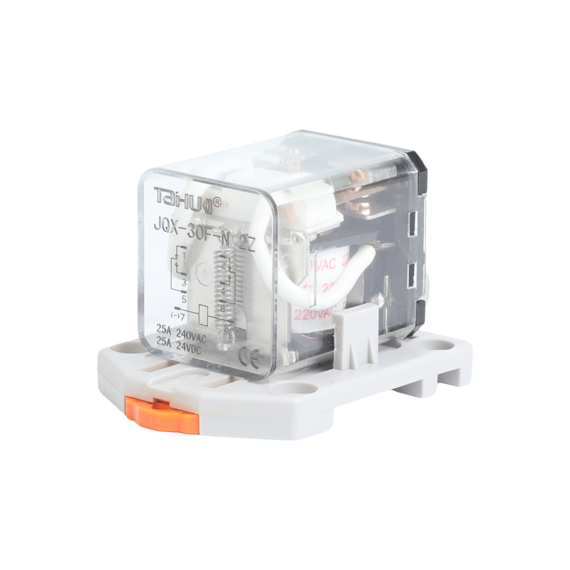
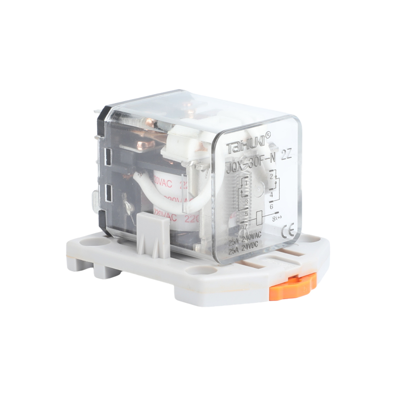
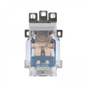
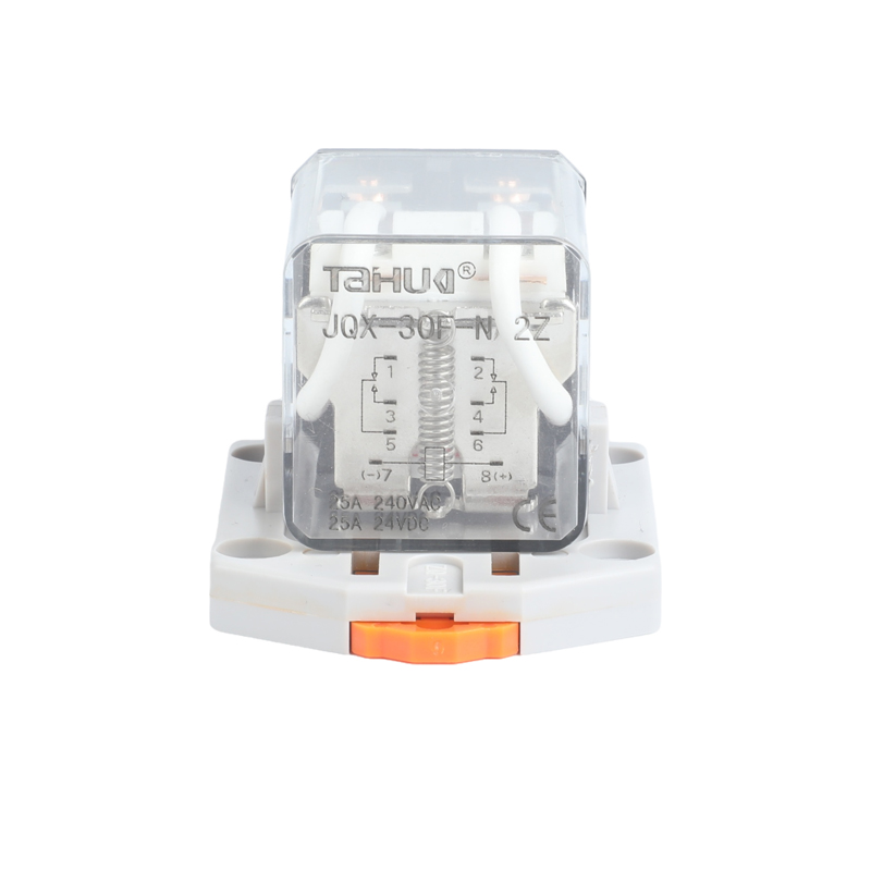
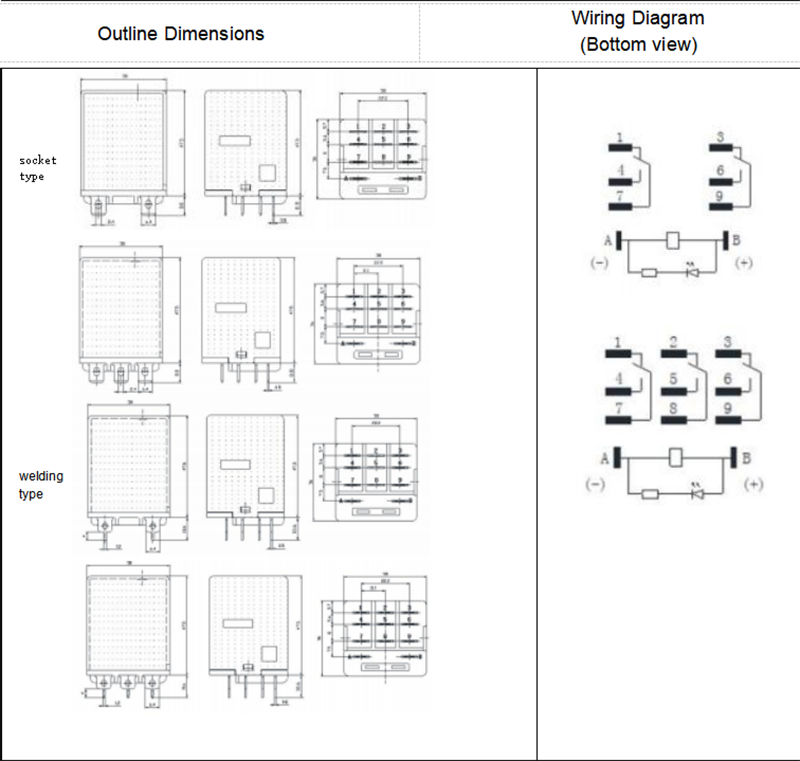
Taihua new type electromagnetic power relay JQX-30F-N with socket
· Firm structure, strong shock and vibration resistance, long service life.
. Load switching current:25A
·2 or 3 sets of contact installation are available.
. Available in socket type, welding type and flange type.
|
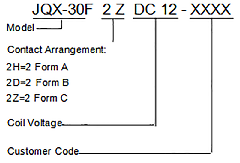
Contact Arrangement |
2H, 2D, 2Z |
3H,3D,3Z |
|
Contact Resistance |
≤ 100mΩ |
|
|
Contact Material |
Silver Alloy |
|
|
Contact Rating(Resistive) |
25A 28VDC; 25A 240VAC |
|
|
Max. Switching Voltage |
240VAC/28VDC |
|
|
Max. Switching Current |
25A |
|
|
Max. Switching Power |
6000VA/700W |
|
|
Mechanical Life |
1×10 6 operations |
|
|
Electrical Life |
5×10⁴ operations |
|
|
Insulation Resistance |
200MΩ (at 500VDC) |
|
|
Dielectric Strength |
Between coil & contacts |
2500VAC 1min |
|
Between open contacts |
1500VAC 1min |
|
|
Operate time (at nomi. volt.) |
≤ 15ms |
|
|
Release time (at nomi. volt.) |
≤ 10ms |
|
|
Humidity |
35% ~ 85% RH |
|
|
Storage Condition |
-25°C~+65°C |
|
|
Operating Condition |
-25°C~+55°C |
|
|
UL Class F |
Insulation System Class F |
|
|
Shock Resistance |
Functional |
98m/s2 |
|
Destructive |
980m/s2 |
|
|
Vibration resistance |
10Hz to 55Hz 1.5mm DA |
|
|
Unit weight |
Approx. 77g |
|
|
Construction |
Dust Cover Type |
|
Notes:1) The data shown above are initial values.
2) Please find coil temperature curve in the characteristic curved below.
This datasheet is for customers' reference. All the specifications are subject to change without notice.
|
Nominal VDC |
Pick-up Voltage (Max.) VDC |
Drop-out Voltage (Min.) VDC |
*Max. Allowable VDC |
Coil Resistance Ω± 10% |
|
12 |
9.00 |
1.2 |
13.2 |
80 |
|
24 |
18.0 |
2.4 |
26.4 |
320 |
|
1 10 |
82.5 |
1 1 |
121 |
1280 |
|
220 |
165.0 |
22 |
242 |
6720 |
|
Nominal VAC |
Pick-up Voltage (Max.) VAC |
Drop-out Voltage (Min.) VAC |
*Max. Allowable VAC |
Coil Resistance Ω± 10% |
|
12 |
9.60 |
3.6 |
13.2 |
20 |
|
24 |
19.2 |
7.2 |
26.4 |
80 |
|
1 10 |
88.0 |
33 |
121 |
320 |
|
220 |
176.0 |
66 |
242 |
6780 |
Note:
"*Max Allowable Voltage" : The relay coil can endure max allowable voltage for a short period time onl
Notes:
1 . PC board assembled with dust cover type and flux tight type relays can not be washed and/or coated.
2. Dust cover type and flux tight type relays can not be used in the environment with dust, or H
|
Coil Power |
DC: 1.8W AC:2.5VA |
This datasheet is for customers' reference. All the specifications are subject to change without notice.
|
flange type |
|
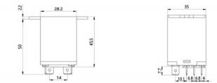
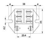
Remark:1) In case of no tolerance shown in outline dimension: outline dimension ≤ 1mm,tolerance should be ±0.2mm; outline dimension >1mm and ≤5mm,tolerance should be ±0.3mm;outline dimension >5mm, tolerance should be ±0.4mm.
2) The tolerance without indicating for PCB layout is always ±0.1mm.