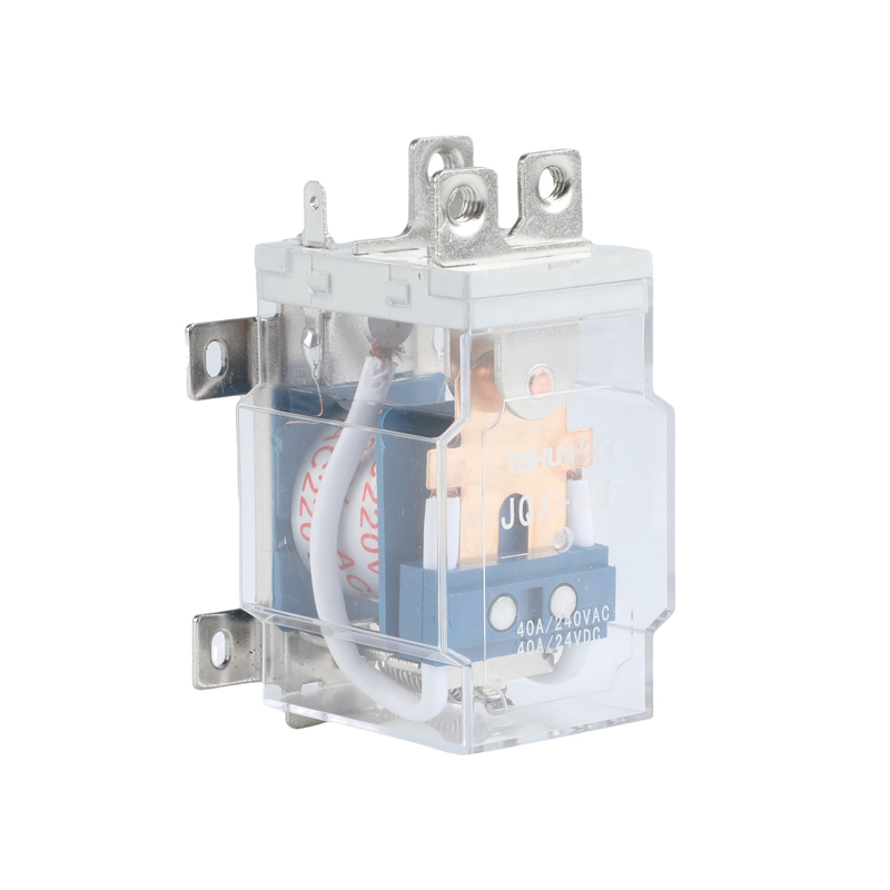
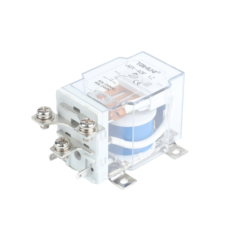
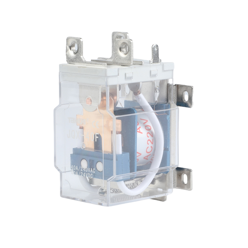
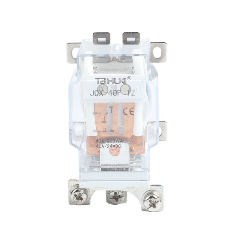
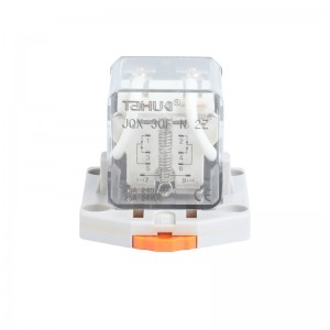
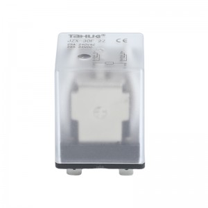
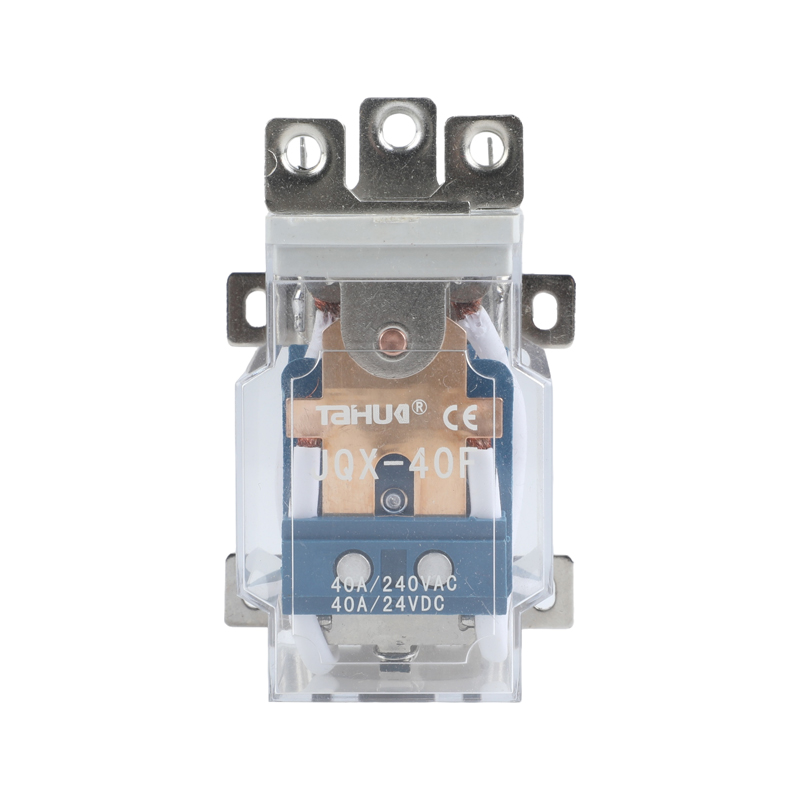
Taihua power relay JQX-40F DC12V DC24V AC220V
·Highly reliable, low cost
·Miniature size & large switch capacity up to 10A
· High dielectric strength type · Fully Sealed
|
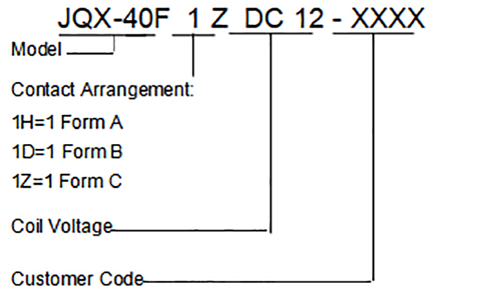
Contact Arrangement |
1H, 1D, 1Z |
|
Contact Resistance |
≤ 100mΩ (1A 24VDC) |
|
Contact Material |
Silver Alloy |
|
Contact Rating(Resistive) |
40A 28VDC; 40A 250VAC |
|
Max. Switching Voltage |
250VAC/28VDC |
|
Max. Switching Current |
40A |
|
Max. Switching Power |
10000VA/1120W |
|
Mechanical Life |
1×10 7 operations |
|
Electrical Life |
3×10⁴ operations |
|
Insulation Resistance |
200MΩ (at 500VDC) |
|
|
Dielectric Strength |
Between coil & contacts |
2500VAC 1min |
|
Between open contacts |
1500VAC 1min |
|
|
Operate time (at nomi. volt.) |
≤25ms |
|
|
Release time (at nomi. volt.) |
≤ 15ms |
|
|
Humidity |
45% ~ 85% RH |
|
|
Storage Condition |
-55°C~+85°C |
|
|
Operating Condition |
-55°C~+70°C |
|
|
UL Class F |
Insulation System Class F |
|
|
Shock Resistance |
Functional |
98m/s2 |
|
Destructive |
980m/s2 |
|
|
Vibration resistance |
10Hz to 55Hz 1.5mm DA |
|
|
Unit weight |
Approx. 110g |
|
|
Construction |
Dust Cover Type |
|
Notes:1) The data shown above are initial values.
2) Please find coil temperature curve in the characteristic curved below.
|
Nominal VDC |
Pick-up Voltage (Max.) VDC |
Drop-out Voltage (Min.) VDC |
*Max. Allowable VDC |
Coil Resistance Ω± 10% |
|
12 |
9.00 |
1.2 |
13.2 |
71.8 |
|
24 |
18.0 |
2.4 |
26.4 |
288 |
|
1 10 |
82.5 |
1 1 |
121 |
6044 |
|
220 |
165.0 |
22 |
242 |
24444 |
|
Nominal VAC |
Pick-up Voltage (Max.) VAC |
Drop-out Voltage (Min.) VAC |
*Max. Allowable VAC |
Coil Resistance Ω± 10% |
|
12 |
9.60 |
3.6 |
13.2 |
12.6 |
|
24 |
19.2 |
7.2 |
26.4 |
50.3 |
|
1 10 |
88.0 |
33 |
121 |
1069 |
|
220 |
176.0 |
66 |
242 |
4254 |
Note:
"*Max Allowable Voltage" : The relay coil can endure max allowable voltage for a short period time onl
Notes:
1 . PC board assembled with dust cover type and flux tight type relays can not be washed and/or coated.
2. Dust cover type and flux tight type relays can not be used in the environment with dust, or H
|
Coil Power |
DC:2.0W AC:4VA |
| Outline Dimensions | Wiring Diagram (Bottom view) | PCB Layout (Bottom view) |
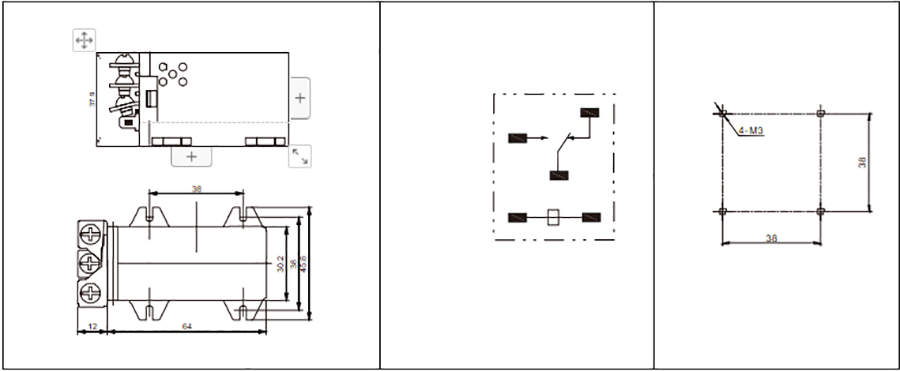
Remark:1) In case of no tolerance shown in outline dimension: outline dimension ≤ 1mm,tolerance should be ±0.2mm; outline dimension >1mm and ≤5mm,tolerance should be ±0.3mm;outline dimension >5mm, tolerance should be ±0.4mm.
2) The tolerance without indicating for PCB layout is always ±0.1mm.